Inverted Pendulum
As part of my control systems course, my teammate and I tackled the challenging task of building an inverted pendulum capable of resisting external disturbances. This hands-on project pushed us to apply the theoretical balancing techniques we studied in class to a real-world engineering problem, all while working within a strict $100 budget constraint.
Our design process began with conceptual sketches, carefully selecting readily available components to balance both affordability and functionality. Recognizing the potential of 3D printing technology, we decided to custom-manufacture our structural components, allowing us to significantly reduce costs while maintaining precise tolerances and professional-quality results.
Through meticulous calibration and iterative test printing, we achieved precision-engineered parts that eliminated the need for traditional fastening hardware. Our innovative approach utilized exclusively friction and interference fits, creating a robust assembly without screws, bolts, or adhesives. This design philosophy not only kept us under budget but also simplified both assembly and future maintenance.
The complete build guide, including detailed diagrams and code repository, is available on my profile for anyone interested in replicating or adapting this control system project. The implementation demonstrates practical applications of control theory while showcasing cost-effective engineering solutions.
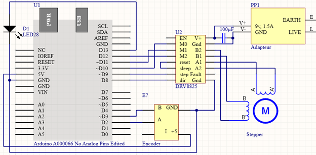
Componants used in the project:- Arduino Uno
- 12V Stepper Motors
- DRV8825 Stepper Motor Driver
- Encoder
- Belt Kit with Pulleys
- 2 x 500mm Linear Rails
- 3D Printed Base
- 3D Printed Pendulum
- Misc. Stainless Steel Hardware, Wires, Wood and Acrylic
By following the diagram below and the repo on my profile you should also be able to build and adapt your own inverted pendulum. Credit to Ian Carey for the bases of the Arduino code.
My inverted pendulum repo Ian Carey inverted pendulum